


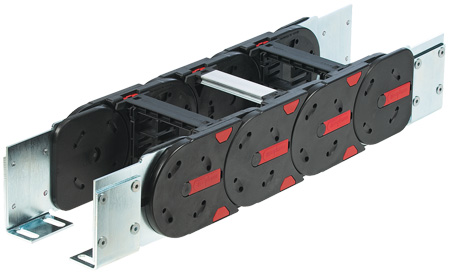
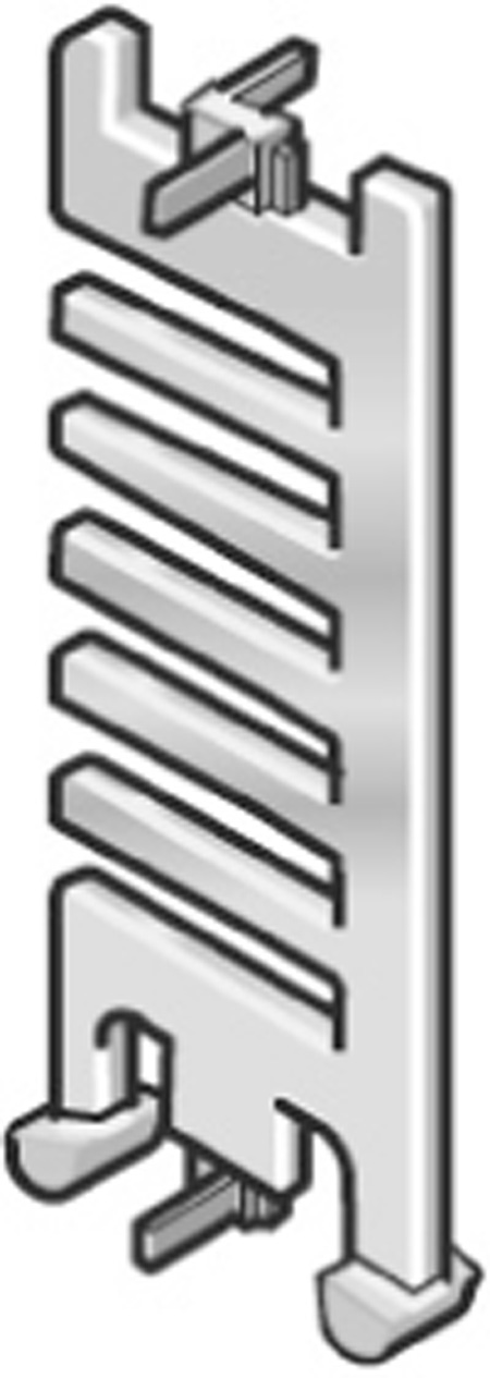
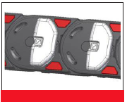
MP 102.2
| Altura interna: | 104 mm |
| Largura interna: | 93 - 518 mm |
| Largura externa: | 139 - 564 mm |
| Raio de curvatura: | 250 - 500 mm |
| Passo: | 141 mm |
| Elos por metro: | 7 |


| Largura interna (A) | Altura interna (B) | Largura externa (D) | Altura externa (C) |
|---|---|---|---|
| 93 mm | 104 mm | 139 mm | 135 mm |
| 106 mm | 104 mm | 152 mm | 135 mm |
| 118 mm | 104 mm | 164 mm | 135 mm |
| 131 mm | 104 mm | 177 mm | 135 mm |
| 143 mm | 104 mm | 189 mm | 135 mm |
| 156 mm | 104 mm | 202 mm | 135 mm |
| 168 mm | 104 mm | 214 mm | 135 mm |
| 181 mm | 104 mm | 227 mm | 135 mm |
| 193 mm | 104 mm | 239 mm | 135 mm |
| 206 mm | 104 mm | 252 mm | 135 mm |
| 218 mm | 104 mm | 264 mm | 135 mm |
| 231 mm | 104 mm | 277 mm | 135 mm |
| 243 mm | 104 mm | 289 mm | 135 mm |
| 256 mm | 104 mm | 302 mm | 135 mm |
| 268 mm | 104 mm | 314 mm | 135 mm |
| 293 mm | 104 mm | 339 mm | 135 mm |
| 318 mm | 104 mm | 364 mm | 135 mm |
| 343 mm | 104 mm | 389 mm | 135 mm |
| 368 mm | 104 mm | 414 mm | 135 mm |
| 418 mm | 104 mm | 464 mm | 135 mm |
| 468 mm | 104 mm | 514 mm | 135 mm |
| 518 mm | 104 mm | 564 mm | 135 mm |
| Raio de curvatura (R) |
|---|
| 250 mm |
| 300 mm |
| 400 mm |
| 500 mm |


Característica do material - Standard (PA/Preto)
| Temperatura de trabalho: | -30 - 120 ° C |
| Fator de fricção-Gliding: | 0.30 |
| Fator de fricção-Estático: | 0.45 |
| Classificação: | In accordance to UL94 HB |
Outras informações
Especificações técnicas
| Distância do curso, Gliding Lg: | 150 m |
| Distância do curso, Autoportante Lf: | Veja o diagrama |
| Distância do curso, fixação suspensa Lvh: | 80 m |
| Distância do curso, fixação vertical Lvs: | 8 m |
| rotação 90 graus não autoportante L90f: | 8 m |
| Velocidade, Gliding Vg: | 5 m /s |
| Velocidade, Não autoportante Vf: | 20 m /s |
| Aceleração, Deslizante ag: | 25 m /s² |
| Aceleração, Não autoportante af: | 40 m /s² |
Comprimento - Auto portante
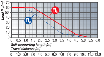
FLg:
Situação ideal de instalação
FLb:
Posição satisfatória de instalação
Determinando o comprimento da esteira

L = Distância do curso
R = Radius
T = Passo
E =
Comprimento = L/2 + π × R + 2 × T + E
1 m chain = 7 x 141 mm links The fixed point of the cable drag chain should be connected in the middle of the travel distance. This arrangement gives the shortest connection between the fixed point and the moving consumer and thus the most efficient chain length.
Peso da esteira
| Peso |
|---|
| 9 kg/m |
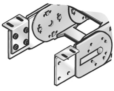
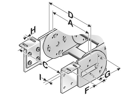
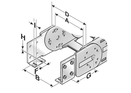
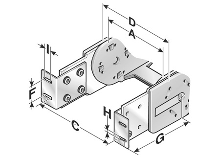
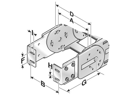
Chain bracket
There are several options regarding the chain bracket. The fixed-point bracket (inside/bottom) and the moving end bracket (inside/top) are supplied as standard. However, any other combination can be supplied upon request. The chain bracket is fastened at the end like a side link. This enables the chain to move right up to the bracket. Each chain requires one male and one female bracket. The brackets should be fastened with M12 screws.| Número da ordem | Tipo | Quantidade por embalagem |
|---|---|---|
| 1020000050 | KA 102 Female end | 1 |
| 1020000051 | KA 102 Male end | 1 |
| Type | Inside width A | Outside width B | Outside width C | D | F | G | G1 | H Ø | I |
|---|---|---|---|---|---|---|---|---|---|
| KA 102 | 118 mm – 518 mm | A + 2 mm | A + 38 mm | A + 46 mm | 50 mm | 95 mm | 187.5 mm | 13 mm | 25 mm |
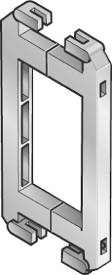
Bottom and top / outside
Bottom and top/inside
Front/Outside
Front/inside
Separator


| Type | Order No. | Designation | Version | TI | TA | H | H1 | H2 | H3 | H4 | H5 | H6 | H7 | HI |
|---|---|---|---|---|---|---|---|---|---|---|---|---|---|---|
| TR 102 | 1020000092 | Separator | lockable | 4 mm | 13 mm | 5.5 mm | 27.6 mm | 39.9 mm | 54.2 mm | 64.7 mm | 77 mm | 89.3 mm | 104 mm | |
| RTT 102 | 100091022000 | Shelf support, divisible | lockable | 8 mm | 8 mm | 5.5 mm | 15.4 mm | 27.6 mm | 39.9 mm | 52.4 mm | 64.7 mm | 77 mm | 89.3 mm | 104 mm |
Crossbar connector
For frame bridges wider than 246 mm, we recommend the use of crossbar connectors. Their use prevents the frame bridge from separating due to the extra load in the chain.

| Type | Order No. | Designation | TI |
|---|---|---|---|
| RSV 102 | 1020000096 | Crossbar connector | 8 mm |
| RSV 102 Alu | 1020000098 | Crossbar connector for aluminium frame bridges | 8 mm |
Shelving system
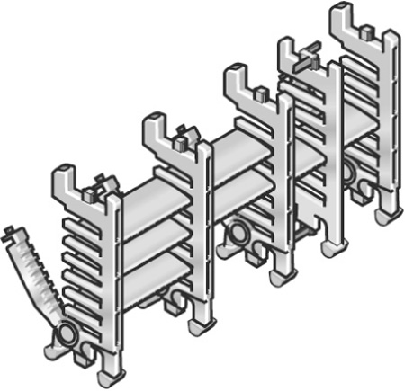
In connection with at least two shelf supports (RTT) the shelf becomes a shelving system. The additional levels prevent cables from criss-crossing and therefore destroying each other, whilst also avoiding excessive friction. The shelving system may be pre-assembled on request.
| Type | Order No. | Width | For inner width |
|---|---|---|---|
| RB 056 - 7 | 100000005600 | 56 mm | 93 mm |
| RB 061 - 7 shelf 061 - 7 mm | 1000006107 | 61 mm | 93 mm |
| RB 066 - 7 | 100000006600 | 66 mm | 93 mm |
| RB 071 - 7 shelf 071 - 7 mm | 1000007107 | 71 mm | 93 mm |
| RB 076 - 7 shelf 076 - 7 mm | 1000007607 | 76 mm | 93 mm |
| RB 081 - 7 | 100000008100 | 81 mm | 93 mm |
| RB 086 - 7 shelf 086 - 7 mm | 1000008607 | 86 mm | 93 mm |
| RB 091 - 7 shelf 091 - 7 mm | 1000009107 | 91 mm | 106 mm |
| RB 096 - 7 shelf 096 - 7 mm | 1000009607 | 96 mm | 106 mm |
| RB 101 - 7 shelf 101 - 7 mm | 1000010107 | 101 mm | 106 mm |
| RB 106 - 7 | 100000010600 | 106 mm | 106 mm |
| RB 111 - 7 shelf 111 - 7 mm | 1000011107 | 111 mm | 118 mm |
| RB 116 - 7 | 100000011600 | 116 mm | 118 mm |
| RB 121 - 7 shelf 121 - 7 mm | 1000012107 | 121 mm | 131 mm |
| RB 126 - 7 shelf 126 - 7 mm | 1000012607 | 126 mm | 131 mm |
| RB 131 - 7 shelf 131 - 7 mm | 1000013107 | 131 mm | 143 mm |
| RB 136 - 7 shelf 136 - 7 mm | 1000013607 | 136 mm | 143 mm |
| RB 141 - 7 shelf 141 - 7 mm | 1000014107 | 141 mm | 143 mm |
| RB 146 - 7 shelf 146 - 7 mm | 1000014607 | 146 mm | 156 mm |
| RB 151 - 7 shelf 151 - 7 mm | 1000015107 | 151 mm | 156 mm |
| RB 156 - 7 shelf 156 - 7 mm | 1000015607 | 156 mm | 156 mm |
| RB 161 - 7 shelf 161 - 7 mm | 1000016107 | 161 mm | 168 mm |
| RB 166 - 7 | 100000016600 | 166 mm | 168 mm |
| RB 171 - 7 shelf 171 - 7 mm | 1000017107 | 171 mm | 181 mm |
| RB 176 - 7 shelf 176 - 7 mm | 1000017607 | 176 mm | 181 mm |
| RB 181 - 7 shelf 181 - 7 mm | 1000018107 | 181 mm | 181 mm |
| RB 186 - 7 shelf 186 - 7 mm | 1000018607 | 186 mm | 193 mm |
| RB 191 - 7 shelf 191 - 7 mm | 1000019107 | 191 mm | 193 mm |
| RB 196 - 7 shelf 196 - 7 mm | 1000019607 | 196 mm | 206 mm |
| RB 201 - 7 shelf 201 - 7 mm | 1000020107 | 201 mm | 206 mm |
| RB 206 - 7 shelf 206 - 7 mm | 1000020607 | 206 mm | 206 mm |
| RB 211 - 7 shelf 211 - 7 mm | 1000021107 | 211 mm | 218 mm |
| RB 216 - 7 | 100000021600 | 216 mm | 218 mm |
Frame bridge strain relief plate RS-ZL
Fixed integrated frame bridge strain relief plates in the chain brackets. Accommodated to all widths of the frame bridges, up to 243 mm in size. May be assembled on the inside and outside bend at both chain endings.
| Type | Order No. | For inner width |
|---|---|---|
| RS-ZL 093 - 7 | 072009300010 | 93 mm |
| RS-ZL 106 - 7 | 072010600010 | 106 mm |
| RS-ZL 118 - 7 | 072011800010 | 118 mm |
| RS-ZL 131 - 7 | 072013100010 | 131 mm |
| RS-ZL 143 - 7 | 072014300010 | 143 mm |
| RS-ZL 156 - 7 | 072015600010 | 156 mm |
| RS-ZL 168 - 7 | 072016800010 | 168 mm |
| RS-ZL 181 - 7 | 072018100010 | 181 mm |
| RS-ZL 193 - 7 | 072019300010 | 193 mm |
| RS-ZL 206 - 7 | 072020600010 | 206 mm |
| RS-ZL 218 - 7 | 072021800010 | 218 mm |
| RS-ZL 231 - 7 | 072023100010 | 231 mm |
| RS-ZL 243 - 7 | 072024300010 | 243 mm |
| RS-ZL 256 - 7 | 072025600010 | 256 mm |
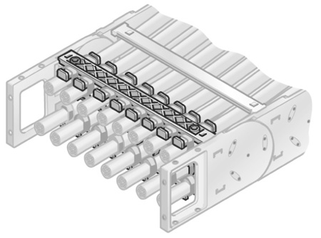
Strain relief with bow clamps

C-rails (cathodic dipped) for permanent integration, for accommodating the Steel Fix bow clamps in the chain brackets. The bow clamps can take up to 3 cables and are suitable for C-rails with a groove width of 11 mm. Due to the design of the trough elements, a cable preserving cable guidance is ensured. May be assembled on the inside and outside bends at both chain endings. The overall height stated is a guide only. The actual height is, amongst other things, dependent on the diameter and the quality of the cable. A safety distance of 10 mm at the fixed point above the strain relief must be kept during gliding applications.
Glide plates
If the installation height is restricted for a horizontal self-supported mounting position, it is recommended to turn installation way of the cable drag chain by 90°.
Among other factors which have to be considered, the lateral abrasion of side links is also very important. We recommend the use of special developed gliding plates to reduce the wear and to extend the service life of the cable drag chain.
We recommend a stainless steel surface for supporting a smooth movement.
| Order No. | Plate height |
|---|---|
| 102290400301 | 7 mm |
Extender frame bridge

Large-diameter conduits are routed securely by using a bracket bar (BS). This bar is installed on the frame bridges or the covers of the cable drag chain. The bracket bar can be installed on both the inside and outside bend. The bracket bar support (BSH) is used to attach the bars to PowerLine series frame bridges. Two bracket bar supports are required for each bar. On closed covers and the frame bridges of the HeavyLine series, the bracket bars are secured with screws.
| Type | Order No. | Designation | Max conduit dia. | Installation height | Min inner chain width |
|---|---|---|---|---|---|
| BS 120 - 5 | 052412000000 | Extender frame bridge | 115 mm | 140 mm | 164 mm |
| BS 153 - 5 | 052415300000 | Extender frame bridge | 148 mm | 170 mm | 208 mm |
| BS 187 - 5 | 052418700000 | Extender frame bridge | 182 mm | 205 mm | 233 mm |
| BSH- 5 | 052400000000 | Extender frame bridge holder |
Rear-facing radius

Side links with radius forward (R) and radius backward (Rü) allow for movement in two directions. This is intended for rotating movements and lowered chain brackets. Note: This type of chain has different chain links for the left or right side!
| Type | Order No. | Radius | Reverse radius |
|---|---|---|---|
| SR 102 (RÜ 400 /R 400 ) left | 10200040060 | 400 mm | 400 mm |
| SR 102 (RÜ 400 /R 400 ) right | 10200040062 | 400 mm | 400 mm |
Guide channel systems for cable drag chains serve as trays for short travel distances and at the same time as guides for long travel distances. If no guide channel is used it is possible that the chain links may lay and move incorrectly. Especially for large bend radii as the side guidance does not exist. In most applications the cables/conduits enter the chain at a position central to the travel. This gives the shortest length of chain. In this case the chain is about half as long as the travel distance. If the chain is moved to the left (see illustration below) it simply rolls in the channel. If it is moved to the right, then it stacks on top of itself once the unsupported length has been exceeded. If the movement is further made into direction B the glide rail adjusts the difference in height and guarantees the minimum possible friction. This ensures the optimum free and correct running of the cable drag chain.
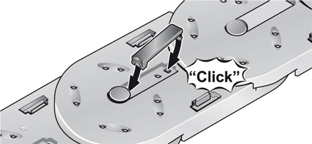
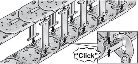
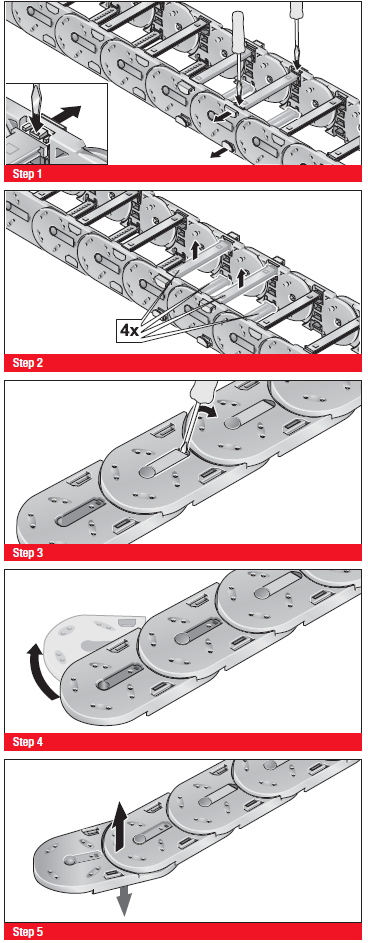
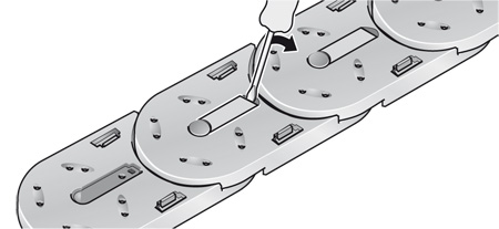
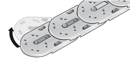
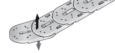
Montagem
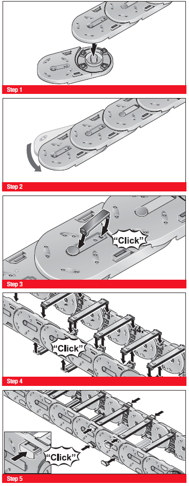
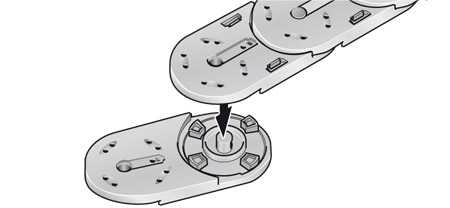
Step 1
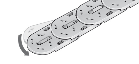
Step 2
Step 3
Step 4
Desmontada
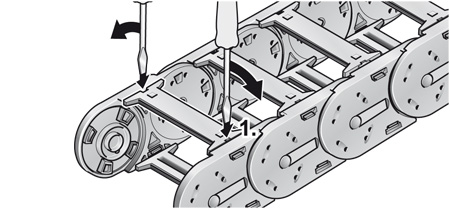
Step 1
Step 2
Step 3
Step 4
- 102.2 Links
- 102.2 End Brackets
- RS ZL strain relief
- MP 102.2 End Brackets
- MP 102.2 Links
- MP 102.2 separators
- RS ZL strain relief
- Frame Bridge extender
- MP 102.2 RB shelf
- MP 102.2 Glide Plate
Caso o formato CAD que você não deseja listar, entre em contato com nossa equipe de suporte.