


MP 44
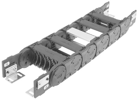
| Internal height: | 40 mm |
| Internal widths: | 45 - 182 mm |
| Outside widths: | 78 - 215 mm |
| Radii: | 90 - 250 mm |
| Pitch: | 75.50 mm |
| Links Per Meter: | 13 |
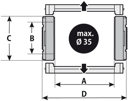

| Interior width (A) | Interior height (B) | Exterior width (D) | Exterior height (C) |
|---|---|---|---|
| 45 mm | 40 mm | 78 mm | 60 mm |
| 62 mm | 40 mm | 95 mm | 60 mm |
| 84 mm | 40 mm | 117 mm | 60 mm |
| 105 mm | 40 mm | 138 mm | 60 mm |
| 144 mm | 40 mm | 177 mm | 60 mm |
| 182 mm | 40 mm | 215 mm | 60 mm |
| Radius (R) |
|---|
| 90 mm |
| 125 mm |
| 150 mm |
| 200 mm |
| 250 mm |


Material characteristics standard (PA/black)
| Service temperature: | -30 - 120 ° C |
| Gliding friction factor: | 0.30 |
| Static friction factor: | 0.45 |
| Fire classification: | In accordance to UL94 HB |
Other information on request
Technical Specifications
| Travel distance, gliding Lg: | 50 m |
| Travel distance, self-supporting Lf: | See Diagram |
| Travel distance, vertical, hanging Lvh: | 40 m |
| Travel distance, vertical, upright Lvs: | 3 m |
| Rotated 90°, unsupported L90f: | 1 m |
| Speed, gliding Vg: | 5 m /s |
| Speed, unsupported Vf: | 15 m /s |
| Acceleration, gliding ag: | 15 m /s² |
| Acceleration, unsupported af: | 20 m /s² |
Self-Supporting Length

FLg:
Ideal installation situation for high stresses at the limit of the max. travel parameters. In this range the chain upper run is still biased, straight or has a max. sag of 10 – 50 mm depending on the type of chain.
FLb:
Satisfactory installation position for many applications working in the lower to middle range of the max. travel parameters. Depending on the chain type, the sag of the chain upper run is > 10 – 50 mm but less than the max. sag. If the sag is greater than FLb, the application is critical and should be avoided. Please choose a more stable Murrplastik cable drag chain.
Determining the Chain Length

L = Travel distance
R = Radius
T = Pitch
E =
Length = L/2 + π × R + 2 × T + E
1 m chain = 13 x 75.5 mm links The fixed point of the cable drag chain should be connected in the middle of the travel distance. This arrangement gives the shortest connection between the fixed point and the moving consumer and thus the most efficient chain length.
Chain Weight
| Weight |
|---|
| 45 kg/m |
| 62 kg/m |
| 84 kg/m |
| 105 kg/m |
| 144 kg/m |
| 182 kg/m |
| 0 kg/m |
| 600 kg/m |
Chain bracket U-part
Special for the 45 mm inside width chain if an inside mounting position is desired. Bracket can be mounted up or down.| Order Number | Type | Pack qty. |
|---|---|---|
| 0440000054 | KA 44 U | 1 |
| Type | Inside width A | Outside width D | F | G | H1 | H2 | I |
|---|---|---|---|---|---|---|---|
| KA 44 U | 45 mm | 78 mm | 28 mm | 45 mm | 6.5 mm | 8.5 mm | 33 mm |
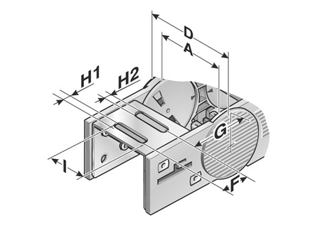
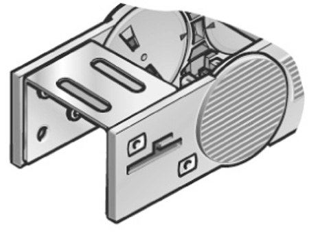
Chain bracket angle
There are several options regarding the chain bracket. The fixed-point bracket (inside/bottom) and the moving end bracket (inside/top) are supplied as standard. However, any other combination can be supplied upon request. The chain bracket is fastened at the end like a side link. This enables the chain to move right up to the bracket. Each chain requires two chain brackets. The brackets should be fastened with M6 screws.| Order Number | Type | Material | Pack qty. |
|---|---|---|---|
| 0440000050 | KA 44 | Sheet steel | 1 |
| 0440000052 | KA 44 | Stainless steel 1.4301 | 1 |
| Type | Inside width A | B | C | Outside width D | F | G | H Ø | I |
|---|---|---|---|---|---|---|---|---|
| KA 44 | 62 mm – 182 mm | A- 14.5 mm | A+ 38.5 mm | A+ 33 mm | 32 mm | 43.2 mm | 6.5 mm | 12.5 mm |
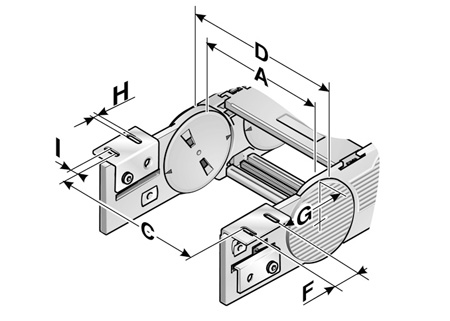
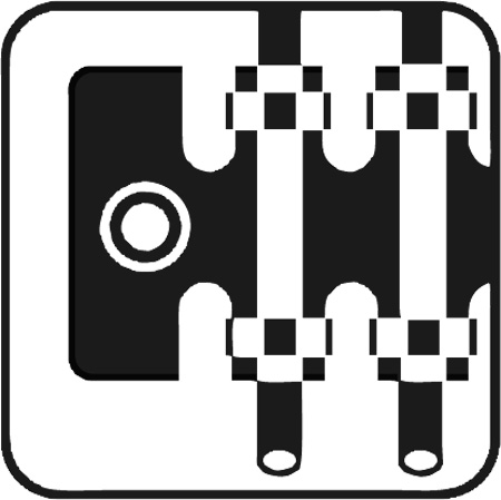
Angle exterior
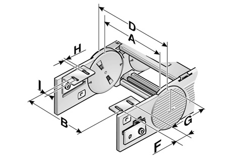
Angle interior
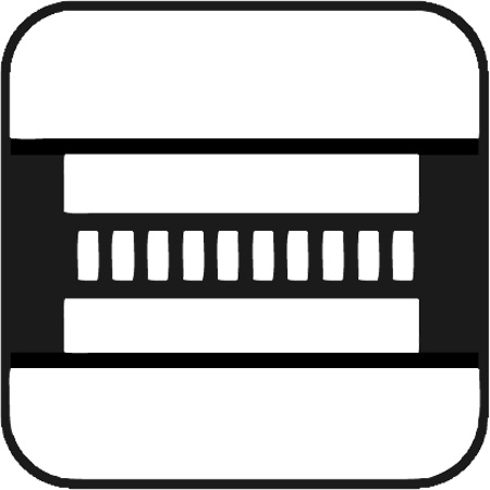
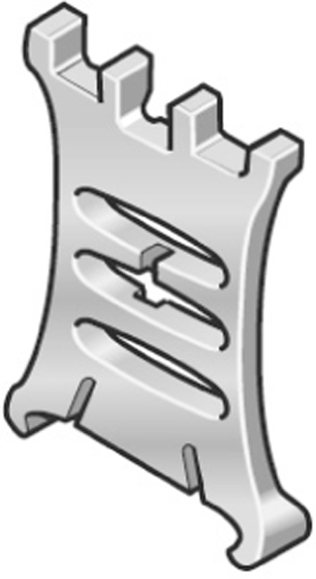
Separator
Shelving system
Guide channel systems for cable drag chains serve as trays for short travel distances and at the same time as guides for long travel distances. If no guide channel is used it is possible that the chain links may lay and move incorrectly. Especially for large bend radii as the side guidance does not exist. In most applications the cables/conduits enter the chain at a position central to the travel. This gives the shortest length of chain. In this case the chain is about half as long as the travel distance. If the chain is moved to the left (see illustration below) it simply rolls in the channel. If it is moved to the right, then it stacks on top of itself once the unsupported length has been exceeded. If the movement is further made into direction B the glide rail adjusts the difference in height and guarantees the minimum possible friction. This ensures the optimum free and correct running of the cable drag chain.
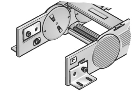
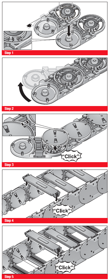
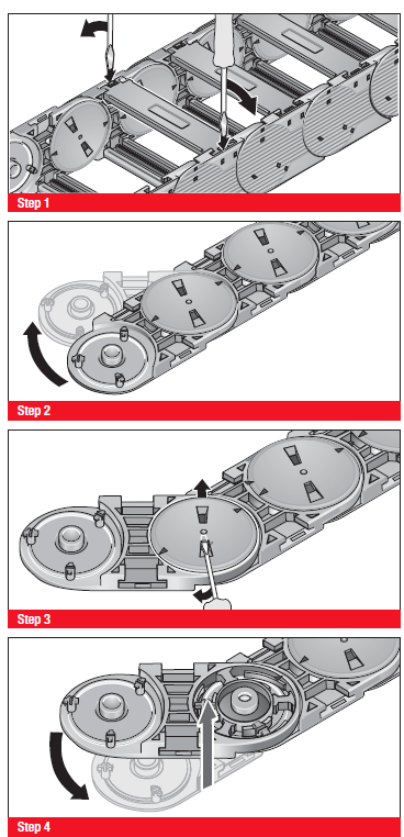
Assembly
Disassembly
Should the CAD format you desire not be listed, please contact our support team.